HDMI Light (4K60 HDR Ambient Lighting)
Completed
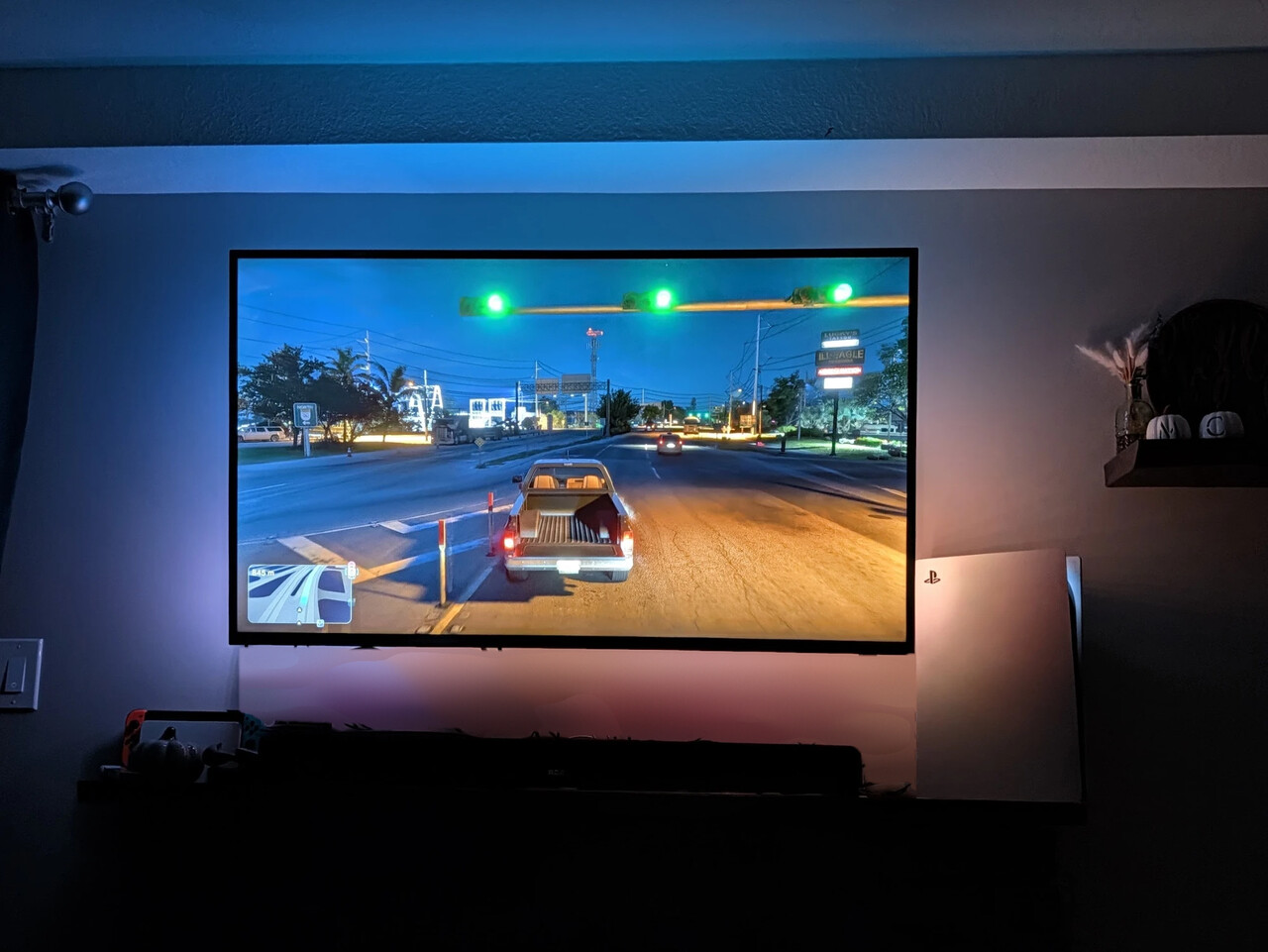
An ESP32-S31 based ambient lighting controller that sits between an HDMI source and a TV and drives an LED strip behind the screen to match the edges of the picture. It handles 4K60 HDR, and needs no PC, no Raspberry Pi and no external splitter or capture dongle.
Features
- 4K60 HDR, HDCP 2.2 support
- GSV2001 HDMI splitter with a built-in downscaler
- MS2130 HDMI to USB capture chip
- ESP32-S31 module decodes the video and drives the LEDs, no waiting for Linux to boot
- HDR tone mapping, black bar detection and smoothing ported from HyperHDR
- Web page for setup, live preview and wireless updates
- Shows up in Home Assistant as a light
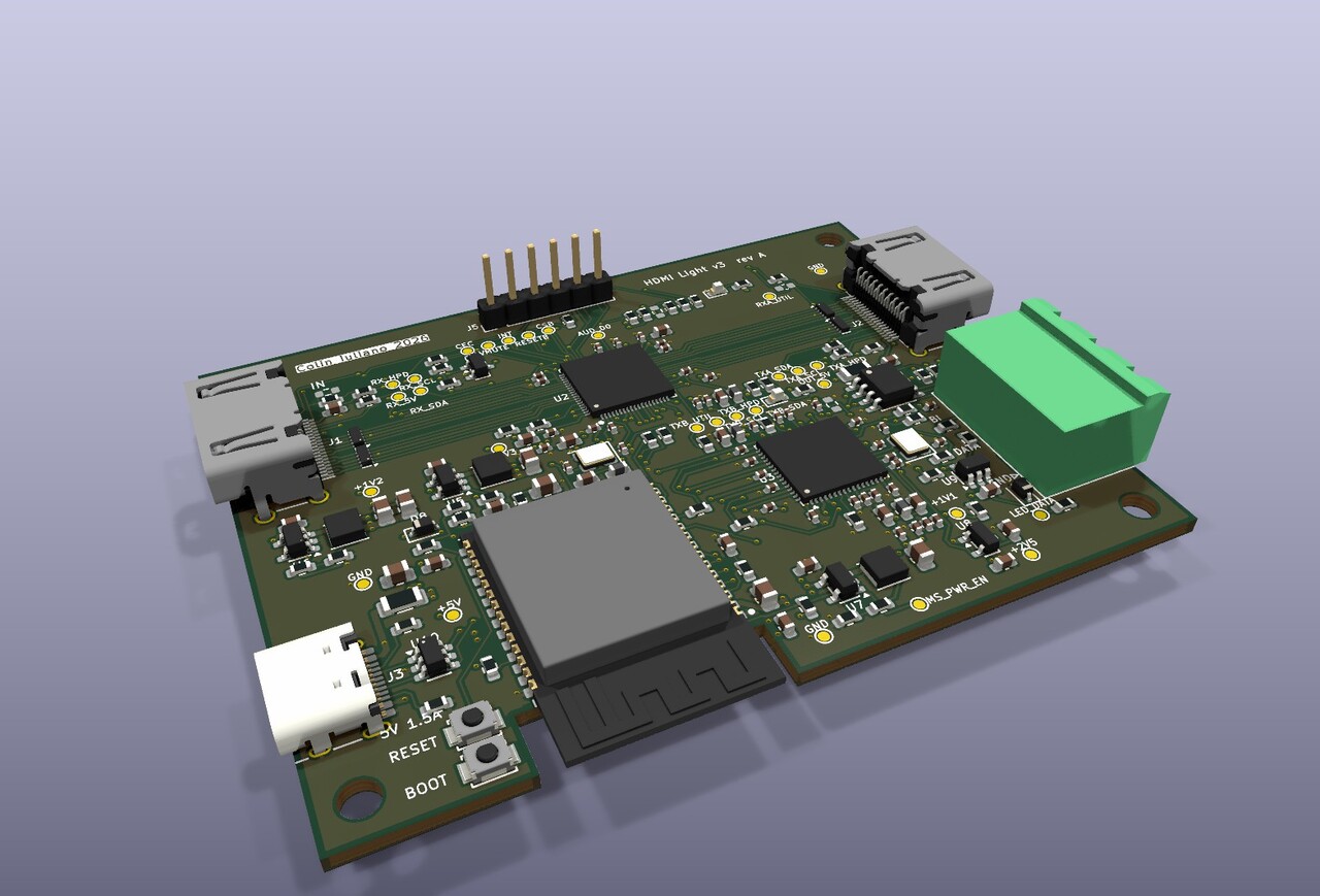
- Custom 4 layer PCB, 78 x 60 mm
- Entirely designed by Claude Fable 5.2
Introduction
DIY ambient lighting on a modern TV is harder than it used to be. Anything that wants to look at the picture has to deal with 4K60, HDR and HDCP 2.2, and the usual answer is a pile of boxes: an HDMI splitter, a USB capture dongle and a Raspberry Pi running HyperHDR. That works, but it is a handful of power supplies and a Linux install hiding behind the TV.
I wanted the whole thing on one small board that never needs attention. The first prototypes used an ESP32 dev kit with a separate splitter and capture dongle, which proved that a microcontroller can decode the video and do the color work fast enough.
This project was mostly completed by Claude Fable 5.2 out of curiosity after they announced that it could create electronics projects. The loose design was tested with a splitter and a capture card, then AI ran with it from there. It suggested which splitter and capture card to use, decompiled firmware, created libraries, made a schematic, designed the PCB, and ran the board bring-up almost entirely by itself. This project took a matter of hours instead of weeks. I blindly ordered the PCB without ever inspecting it, and it worked first try.
Hardware
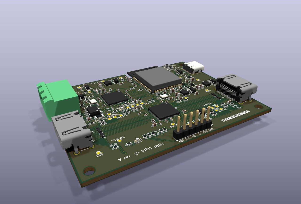
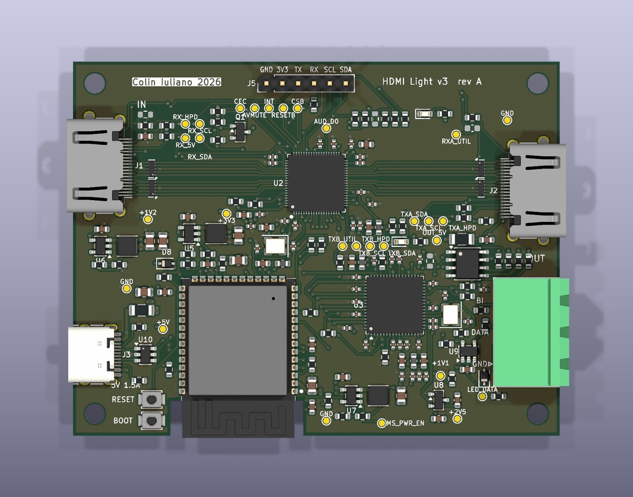
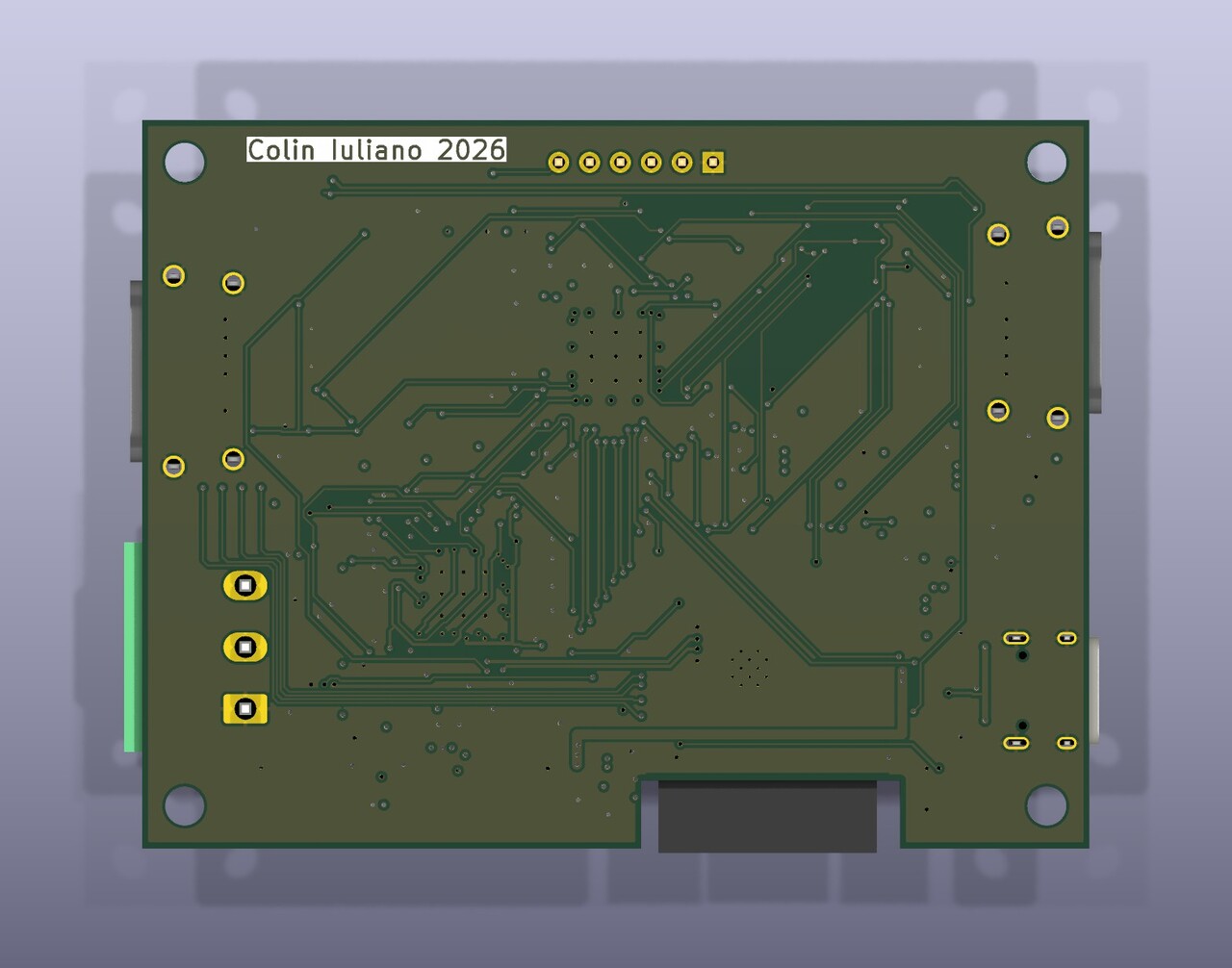
HDMI Splitter
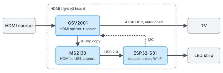
No capture chip with a loop-out output can do this job on its own. A 4K streaming source insists on HDCP 2.2, and the capture chips that can pass 4K60 through will not hand that picture to USB. So the board has a real splitter chip in front of the capture chip.
The Gscoolink GSV2001 has one input, two outputs, and a built-in downscaler. One output passes the input to the TV untouched. The other runs through the scaler, which halves 4K to 1080p since the capture chip can’t do more than 30 fps at 4K. It’s a chip that I could only find on AliExpress.
Capture Chip
The MacroSilicon MS2130 is the chip inside most of the cheap HDMI to USB capture dongles. It takes the 1080p copy from the splitter and shows up on USB as a webcam. The ESP32-S31 only asks it for 640x480 MJPEG at 30 fps, which is plenty for averaging the edges of the screen into LED colors, and keeps CPU usage low.
The chip boots from a small SPI flash that arrives blank, and with a blank flash it never appears on USB at all. The ESP32-S31 is wired to that flash as well, so it can switch off the capture chip’s core and write the image itself.
Controller
An ESP32-S31 module runs everything: it is the USB host for the capture chip, it runs the splitter over I2C, it decodes the video, computes the LED colors and serves the web page. A level shifter drives the LED strip data line at 5 V.
PCB
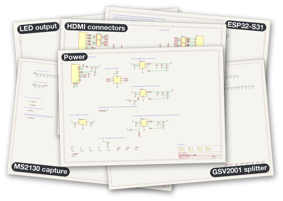
The board was not drawn in a schematic editor, but built by Claude Fable 5.2. A Python script holds every part and net, and more scripts place the parts, route the tracks and write out the KiCad project and the files for JLCPCB. The HDMI pairs are routed at 100 ohms on a 4 layer stackup. JLCPCB assembled everything except the splitter chip (only available on AliExpress) and the ESP32-S31 module (same, difficult to source as of writing).
Schematic
Firmware
Color Pipeline
The color work is a port of HyperHDR to plain C: YUV conversion, HDR tone mapping, averaging each LED’s zone in linear light, black bar detection and smoothing. HyperHDR uses a 50 MB lookup table for tone mapping, which obviously does not fit, so the firmware bakes a much smaller one from the same calibration model. The port is checked against HyperHDR’s own source code on a PC.
Decoding a frame takes about 8 ms and the color pipeline about 12 ms, so 30 fps leaves room to spare. Only the parts of the picture that an LED actually looks at are processed.
Driving the Splitter
This was the hard part. Gscoolink does not publish a register map or an SDK for the GSV2001, and the chip does nothing useful until a microcontroller walks it through hot plug, EDID, locking onto the signal and HDCP.
Several commercial HDMI products use the same chip family, and their firmware updates are public. AI decompiled three of them and rewrote the vendor’s driver in portable C. To be sure the rewrite was right before trusting it with real hardware, the original firmware runs in an emulator against a model of the chip, and every I2C transfer it makes is compared with what the rewritten driver does in the same situation. Eighteen scenarios match byte for byte.
Web Interface
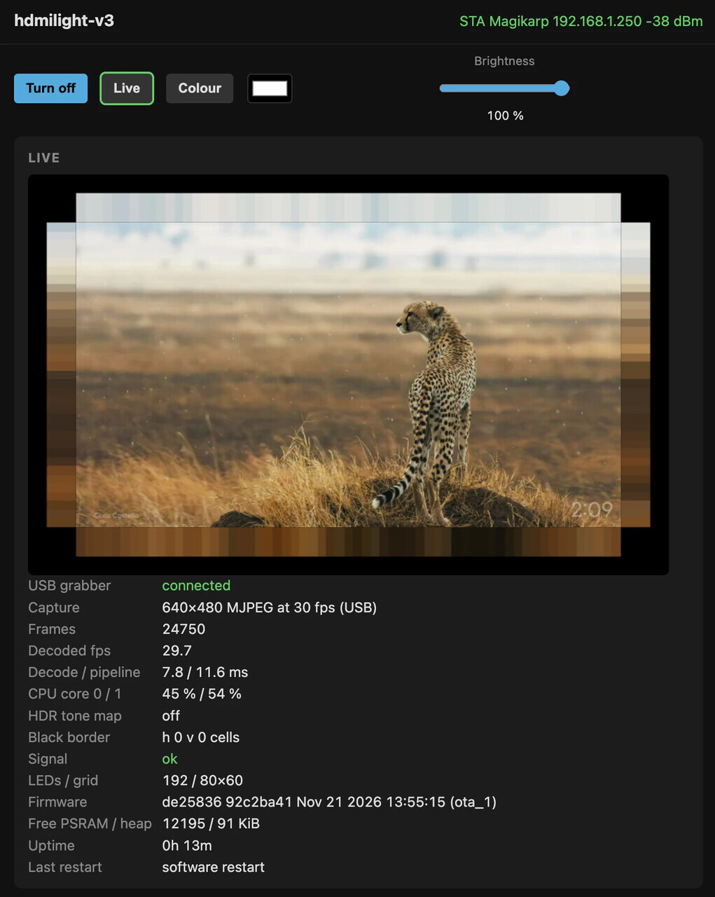
The board serves its own page. It shows the captured picture with the LED colors drawn around it, and has the strip layout, brightness, smoothing, color and HDR settings. Firmware updates go over Wi-Fi into a second slot, and an update that fails to get back on the network is rolled back automatically. Home Assistant sees the board as a light it can turn on and off and dim.
The LEDs never depend on the network. If Wi-Fi goes away the board keeps working and just keeps trying to reconnect.
Results
It works incredibly, on the first try. All issues were diagnosed by AI using HDMI output from a laptop and a capture card back in. After a couple of bad joints were fixed (AI diagnosed them, partly from the splitter chip’s own signal quality readings for each lane), and a few software tweaks were applied (AI copied a product with a lower resolution originally), bring-up was successful and the whole project runs flawlessly.
The board sits behind my TV with 192 LEDs, takes 4K60 HDR from the source and passes it straight through to the TV.